 +86 18578756148


0102030405
Products

01
view
detail
Yuchai SX12 Distributor Valve 60 65 80 85 Lovol...
2025-12-13
|
1.Product Name: |
|
|
2.Part number: |
|
|
3.Compatible For: |
Yuchai60 70 |
|
4.Leading time: |
2-3 days |
|
5.Packing way: |
Neutral packing or CAT Genuine Part Packing |
|
6.Price: |
USD1720 |


03
view
detail
SY16C SY18C SY26 Final Drive Travel Motor Assy ...
2025-12-12
Daily visual inspection – Check for external leaks, damage, or loose connections.
Monitor hydraulic oil level and cleanliness – Ensure proper oil quality and quantity.
Check final drive oil level – Verify oil level in the reduction gearbox.
Listen for unusual noises – Grinding, knocking, or whining sounds indicate issues.
Inspect mounting bolts – Ensure all fasteners are tight and secure.
Monitor travel performance – Note any slipping, uneven movement, or loss of power.
Check for overheating – Touch the motor housing (safely) after operation.
Inspect breathers and vents – Ensure they are clean and unclogged.
Examine travel chains and sprockets – Look for excessive wear or misalignment.
Verify track tension – Proper tension reduces stress on the motor.
Avoid sharp turns on hard surfaces – Minimize stress on the travel system.
Prevent contamination – Keep the area around seals and connections clean.
Operate smoothly – Avoid sudden starts, stops, or direction changes.
Check case drain flow – Ensure minimal leakage from the drain port.
Monitor system pressure – Abnormal pressure may indicate motor or pump issues.
Inspect electrical connections – For electrically controlled motors, check wiring.
Lubricate external linkages – Grease pivot points as per manual.
Avoid continuous high-speed travel – Especially on inclines or rough terrain.
Check parking brake function – Ensure it holds securely on slopes.
Inspect anti-rotation devices – Ensure they are intact and functional.
Record operating hours – Schedule maintenance based on service intervals.
Use correct hydraulic oil – Follow manufacturer’s viscosity and grade recommendations.
Bleed air from the system – If the motor feels spongy or weak.
Check alignment with final drive – Misalignment causes premature wear.
Monitor for oil contamination – Metal particles in oil indicate internal wear.
Inspect seal surfaces – Look for scratches or damage that could cause leaks.
Avoid overloading – Do not exceed the machine’s travel capacity.
Keep travel paths clear – Remove debris that could jam the tracks or sprockets.
Train operators – Ensure proper use and early problem recognition.
Follow manufacturer’s maintenance schedule – Adhere to recommended service intervals for oil changes, filter replacements, and inspections.

04
view
detail
TM40 Final Drive 31N6-40050 Final Drive With Tr...
2025-12-12
Daily visual inspection – Check for external leaks, damage, or loose connections.
Monitor hydraulic oil level and cleanliness – Ensure proper oil quality and quantity.
Check final drive oil level – Verify oil level in the reduction gearbox.
Listen for unusual noises – Grinding, knocking, or whining sounds indicate issues.
Inspect mounting bolts – Ensure all fasteners are tight and secure.
Monitor travel performance – Note any slipping, uneven movement, or loss of power.
Check for overheating – Touch the motor housing (safely) after operation.
Inspect breathers and vents – Ensure they are clean and unclogged.
Examine travel chains and sprockets – Look for excessive wear or misalignment.
Verify track tension – Proper tension reduces stress on the motor.
Avoid sharp turns on hard surfaces – Minimize stress on the travel system.
Prevent contamination – Keep the area around seals and connections clean.
Operate smoothly – Avoid sudden starts, stops, or direction changes.
Check case drain flow – Ensure minimal leakage from the drain port.
Monitor system pressure – Abnormal pressure may indicate motor or pump issues.
Inspect electrical connections – For electrically controlled motors, check wiring.
Lubricate external linkages – Grease pivot points as per manual.
Avoid continuous high-speed travel – Especially on inclines or rough terrain.
Check parking brake function – Ensure it holds securely on slopes.
Inspect anti-rotation devices – Ensure they are intact and functional.
Record operating hours – Schedule maintenance based on service intervals.
Use correct hydraulic oil – Follow manufacturer’s viscosity and grade recommendations.
Bleed air from the system – If the motor feels spongy or weak.
Check alignment with final drive – Misalignment causes premature wear.
Monitor for oil contamination – Metal particles in oil indicate internal wear.
Inspect seal surfaces – Look for scratches or damage that could cause leaks.
Avoid overloading – Do not exceed the machine’s travel capacity.
Keep travel paths clear – Remove debris that could jam the tracks or sprockets.
Train operators – Ensure proper use and early problem recognition.
Follow manufacturer’s maintenance schedule – Adhere to recommended service intervals for oil changes, filter replacements, and inspections.

05
view
detail
XCMG Excavator XE80 85 90 95 105 115 Traveling ...
2025-12-12
Hydraulic travel motors – Provide rotary power to the track wheels.
Dual independent motors – Allow for counter-rotation and pivot turns.
Travel control levers/pedals – Operator inputs for speed and direction.
Main hydraulic pump – Supplies high-pressure oil to the travel system.
Travel control valves – Direct flow from the pump to the left or right motor.
Two-speed travel selection – Switches between high-speed and high-torque modes.
Speed change valve – Alters motor displacement for speed shifting.
Travel reduction gearbox (final drive) – Reduces motor speed and increases torque.
Sprocket drive – Final drive output shaft directly turns the track sprocket.
Planetary gear sets – Inside the reduction gearbox for compact torque multiplication.
Swing bearings – Support the upper structure and allow it to rotate during travel turns.
Track frame – Rigid structure housing the final drive and rollers.
Hydraulic pressure release – Allows the machine to be towed by disengaging the motors.
Travel brakes – Typically spring-applied, hydraulic-release parking brakes.
Hydraulic counterbalance valves – Prevent uncontrolled movement on slopes.
Pilot pressure system – Provides low-pressure control signals to the main valves.
Neutral bypass – Routes pump flow back to tank when travel levers are not activated.
Load sensing system – Adjusts pump flow and pressure based on demand.
Track tension adjustment – Maintains proper tension via grease cylinders.
Track rollers and idlers – Support and guide the track chain.
Pivot turn (spot turn) – Achieved by driving one track forward and the other reverse.
Gradual turn – Accomplished by varying speed between the two tracks.
Straight-line travel – Both motors receive equal flow and pressure.
Auto-deceleration system – Redects engine speed when travel levers are neutral.
Travel alarm – Sounds when the machine is set to move.
Speed sensors (if equipped) – Monitor track speed for control or monitoring systems.
Travel pressure relief valves – Protect the system from overloads.
Case drain lines – Return internal leakage oil from motors back to the tank.
Hydrostatic transmission principle – Uses variable hydraulic flow for infinite speed control.
Integrated pump-motor circuit – Forms a closed-loop for efficient power transfer.

06
view
detail
E320 320 E323 323 E325 325 E329D Excavator Cont...
2025-12-11
Main hydraulic control valve – Directs system flow to all implement functions.
Load sensing system integration – Works with pumps to deliver demand-based flow.
Parallel hydraulic circuit design – Allows simultaneous operation of multiple functions.
Pressure-compensated spool design – Maintains consistent speed under varying loads.
Pilot-operated valve control – Uses low-pressure signals for precise valve actuation.
Independent metering capability – Manages oil flow to both sides of cylinders independently.
Boom regeneration circuit – Improves boom lowering speed and efficiency.
Arm regeneration circuit – Enhances arm retraction speed and energy savings.
Swing priority function – Diverts flow to swing during combined operations.
Attachment flow control – Regulates oil to auxiliary hydraulic circuits for tools.
Anti-cavitation valves – Prevents vacuum formation in cylinders.
Cross-line relief valves – Protects circuits from shock loads during abrupt stops.
Make-up valve function – Supplies oil to prevent vacuum during fast cylinder movement.
Fine control characteristics – Allows precise movements for grading and finishing.
Detent mechanism – Holds valves for continuous operation (e.g., for travel or hammer).
Neutral bypass passage – Directs unused pump flow back to tank with minimal pressure.
Port relief valves – Protect individual cylinders from overpressure.
Load check valves – Hold cylinder positions when levers are in neutral.
Stackable modular design – Simplifies maintenance and function expansion.
Cast iron or ductile iron body – Provides durability and pressure resistance.
Hardened steel spools and sleeves – Ensures long service life with minimal leakage.
Integrated test ports – For system diagnostics and pressure measurement.
Float function capability – Allows attachment to follow ground contours.
Return line to hydraulic tank – Channels spent oil back for cooling and filtration.
Compatibility with load-sensing pumps – Forms efficient closed-center system.
Shock absorption design – Reduces hydraulic hammer during valve shifting.
Multi-function parallel operation – Enables smooth combined movements.
Electronic control interface option – For advanced models with electronic controls.
Proportional priority control – Adjusts flow distribution based on demand.
Core hydraulic management component – Essential for all digging, lifting, and swing operations.

07
view
detail
Excavator Parts XCMG XE470 XE490 XE550 Excavato...
2025-12-10
E01 / Engine overspeed - Engine RPM exceeds maximum allowable limit.
E02 / Engine underspeed - Engine RPM drops below minimum threshold.
P0087 / Low fuel rail pressure - Insufficient high-pressure fuel supply.
P0088 / High fuel rail pressure - Excessive pressure in common rail system.
P0191 / Fuel rail pressure sensor fault - Sensor signal implausible or out of range.
P0234 / Turbo overboost - Turbocharger boost pressure too high.
P0504 / Brake pedal sensor mismatch - Conflicting signals from brake switches.
P0606 / ECU internal error - Engine control module processor fault.
U0073 / CAN bus communication failure - Controller communication network disruption.
U0100 / Lost communication with ECU - No data from engine control module.
CA111 / Hydraulic pump pressure sensor fault - Main pump pressure signal abnormal.
CA211 / Swing system pressure sensor error - Swing circuit pressure reading fault.
CA222 / Travel pressure imbalance - Left/right travel circuit pressure difference too high.
CA456 / Pilot pressure sensor failure - Control pilot pressure signal missing.
CA678 / Proportional valve coil fault - Solenoid valve circuit open or shorted.
Err01 / Display internal communication error - Screen module data transfer failure.
Err02 / Display calibration data lost - Screen calibration parameters corrupted.
Err03 / Keypad input error - Operator button signal abnormal.
F01 / Monitor power supply voltage low - Display operating voltage insufficient.
F02 / Monitor internal temperature high - Display overheating protection triggered.
HP01 / Main hydraulic pump displacement sensor fault - Pump angle feedback error.
HP02 / Pump controller communication failure - Pump ECU data link interrupted.
BD01 / Battery voltage low - System voltage below operating threshold.
BD02 / Alternator charging fault - No or insufficient charging detected.
W01 / Engine coolant temperature high - Cooling system overheating.
W02 / Engine oil pressure low - Insufficient lubrication pressure.
W03 / Hydraulic oil temperature high - Hydraulic system overheating.
W04 / Air filter clogged - Intake restriction indicator activated.
W05 / Fuel filter restriction - Fuel pre-filter requires replacement.
W06 / Water in fuel - Water separator warning.
SA01 / Swing parking brake fault - Brake solenoid or circuit malfunction.
SA02 / Travel alarm failure - Travel warning system fault.
C100 / CAN node configuration error - Network device configuration mismatch.
C101 / CAN bus off - Communication bus completely inactive.
L01 / Left joystick sensor fault - Control lever position signal error.
L02 / Right joystick sensor fault - Right lever feedback abnormal.
A001 / Accelerator pedal sensor fault - Throttle position sensor malfunction.
A002 / Throttle motor driver error - Engine speed actuator failure.
D001 / Diagnostic mode active - System in diagnostic programming state.
D002 / Immobilizer system fault - Security system preventing start.
B100 / Boom raising pressure sensor fault - Boom circuit pressure sensor error.
B200 / Arm cylinder sensor error - Arm position or pressure signal fault.
B300 / Bucket angle sensor fault - Bucket position feedback lost.

08
view
detail
Kubota 15 20 Series Air Filter Air Filter Hou...
2025-12-10
Primary air filtration - Removes dust and abrasive particles from intake air.
Engine protection - Prevents contaminants from entering the combustion chamber.
Dust particle capture - Traps dirt, sand, and soot before they reach the engine.
Ensuring clean airflow - Supplies filtered air for efficient combustion.
Preventing internal wear - Protects cylinder walls, pistons, and rings from abrasion.
Extending engine life - Reduces long-term wear and tear on internal components.
Maintaining compression - Helps preserve piston ring and cylinder liner integrity.
Optimizing fuel combustion - Allows precise air-fuel mixing for complete burning.
Reducing carbon deposits - Minimizes soot formation in cylinders and valves.
Improving fuel efficiency - Enables leaner and more efficient combustion.
Lowering emissions - Reduces particulate matter (PM) and smoke output.
Temperature moderation - Helps stabilize intake air temperature in some designs.
Moisture separation - Some designs help separate water droplets from humid air.
Reducing engine noise - Dampens certain intake pulsation and airflow noises.
Pressure drop management - Designed to minimize restriction to airflow.
Pre-filter stage - Many include a pre-cleaner for large debris.
Safety indicator - Some have a restriction gauge to signal when to service.
Fire prevention - Can act as a flame trap in case of backfire.
Insect and debris barrier - Prevents leaves, insects, or litter from entering.
Maintaining turbocharger health - Protects turbo impeller blades from damage.
Oil bath filtration (older models) - Uses oil to trap particles in some systems.
Pollen filtration - Removes airborne pollen and fine organic matter.
Mold spore prevention - Reduces biological contaminants in the intake.
Ensuring EGR system efficiency - Provides clean air for exhaust gas recirculation.
Supporting sensor accuracy - Protects MAF or MAP sensors from contamination.
Preventing intake valve deposits - Reduces buildup on valve stems and seats.
Maintaining idle stability - Ensures consistent air supply for smooth idling.
Cold start aid - In some systems, it houses pre-heater or intake heater elements.
Rain and snow ingestion prevention - Designed to resist water entry.
Fuel vapor management - In closed systems, it integrates with crankcase ventilation.
Dust storage capacity - Holds captured dust until service.
Vibration resistance - Mounted to withstand engine vibrations.
Heat resistance - Materials tolerate underhood temperatures.
Chemical resistance - Withstands exposure to oils and fuels.
Serviceability design - Allows easy filter inspection and replacement.
Seal integrity - Gaskets prevent unfiltered air bypass.
Housing protection - Shields the filter element from physical damage.
Resonator function - Some housings are tuned to reduce specific frequency noise.
Airflow direction control - Guides air smoothly into the intake manifold.
Water drain provision - Some have drains to expel accumulated moisture.
Winter/summer mode adjustment - Older systems may have a cold weather intake pre-heat.
Supporting aftertreatment systems - Clean air is crucial for DPF and SCR function.
Preventing intercooler contamination - In turbocharged engines, keeps the intercooler clean.
Reducing maintenance frequency - Protects engine oil from becoming contaminated as quickly.
Corrosion prevention - Less abrasive particles mean less corrosion in intake tracts.
Altitude compensation support - Provides consistent air density measurement for ECM.
Reducing exhaust valve wear - Indirectly by ensuring clean combustion.

09
view
detail
PHV-390-53B Walking/Travel Device Komatsu Cater...
2025-12-10
Hydraulic travel motors – Provide rotary power to the track wheels.
Dual independent motors – Allow for counter-rotation and pivot turns.
Travel control levers/pedals – Operator inputs for speed and direction.
Main hydraulic pump – Supplies high-pressure oil to the travel system.
Travel control valves – Direct flow from the pump to the left or right motor.
Two-speed travel selection – Switches between high-speed and high-torque modes.
Speed change valve – Alters motor displacement for speed shifting.
Travel reduction gearbox (final drive) – Reduces motor speed and increases torque.
Sprocket drive – Final drive output shaft directly turns the track sprocket.
Planetary gear sets – Inside the reduction gearbox for compact torque multiplication.
Swing bearings – Support the upper structure and allow it to rotate during travel turns.
Track frame – Rigid structure housing the final drive and rollers.
Hydraulic pressure release – Allows the machine to be towed by disengaging the motors.
Travel brakes – Typically spring-applied, hydraulic-release parking brakes.
Hydraulic counterbalance valves – Prevent uncontrolled movement on slopes.
Pilot pressure system – Provides low-pressure control signals to the main valves.
Neutral bypass – Routes pump flow back to tank when travel levers are not activated.
Load sensing system – Adjusts pump flow and pressure based on demand.
Track tension adjustment – Maintains proper tension via grease cylinders.
Track rollers and idlers – Support and guide the track chain.
Pivot turn (spot turn) – Achieved by driving one track forward and the other reverse.
Gradual turn – Accomplished by varying speed between the two tracks.
Straight-line travel – Both motors receive equal flow and pressure.
Auto-deceleration system – Redects engine speed when travel levers are neutral.
Travel alarm – Sounds when the machine is set to move.
Speed sensors (if equipped) – Monitor track speed for control or monitoring systems.
Travel pressure relief valves – Protect the system from overloads.
Case drain lines – Return internal leakage oil from motors back to the tank.
Hydrostatic transmission principle – Uses variable hydraulic flow for infinite speed control.
Integrated pump-motor circuit – Forms a closed-loop for efficient power transfer.

10
view
detail
Hydraulic Distribution Valve for XCMG 60 Constr...
2025-07-05
|
1.Product Name: |
|
|
2.Part number: |
|
|
3.Compatible For: |
|
|
4.Leading time: |
1-3 days |
|
5.Packing way: |
Neutral packing or CAT Genuine Part Packing |
|
6.Price: |
USD1720 |
11
view
detail
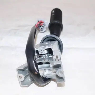
Forward & Reverse Column Switch 70180296 For JC...
2025-08-04
|
1.Product Name: |
Forward/ Reverse Column Switch |
|
2.Part number: |
70180296 |
|
3.Compatible For: |
JCB 3CX 4CX |
|
4.Leading time: |
2-3 days |
|
5.Packing way: |
Neutral packing or CAT Genuine Part Packing |